
Xenon-129
Low pressure, flowing gas, and a column over five feet long
The design follows from a set of facts about rubidium and xenon. These facts favor a long column with flowing gas over a sealed glass cell.
How it was done before
Noble gases are polarized by spin-exchange optical pumping. A laser polarizes the electrons of rubidium vapor. Collisions then transfer that polarization to the nuclei of the xenon or helium mixed with the vapor.
Through the 1990s this was done in glass cells about the size of a fist, cylindrical or spherical. The glass surfaces could be treated to give long wall-relaxation times. To produce more gas, researchers raised the pressure in the cell. The strength of the glass limited the pressure.
Designs of that period kept the surface area small, because surfaces cause wall relaxation. Most hard surfaces that conduct heat were known to accelerate spin relaxation. Polarizing chambers were therefore made as blown glass cells. Glass conducts heat poorly. The heat deposited by the laser limited the laser power that a glass cell could use.
Observations
- Spin exchange between rubidium and xenon is fast at low pressure.
- Xenon also depolarizes rubidium through spin-destruction collisions. The laser can keep the rubidium polarized only where the partial pressure of xenon is low.
- At low pressure the chamber holds little gas at any moment. To produce useful quantities, the gas must be replaced about every half-minute.
- Higher rubidium density raises the spin-exchange rate between rubidium and xenon. More laser power can then be used to polarize the rubidium.
- Spin exchange also works in reverse. Outside the laser light, rubidium depolarizes within milliseconds and then draws down the polarization of the xenon.
- The heat from the laser must leave through the walls. The walls cannot be colder than the condensation temperature of rubidium. The chamber therefore needs more wall area, balanced against wall relaxation.
At low pressure the gas must flow. It must also stay in the laser light for the whole half-minute. These two requirements lead to a long column in place of a cell. The observations on rubidium and heat shaped the column’s thermal design, described below.
The counterflow column
Our polarizing chamber is over five feet long. The gas flows through it in the direction opposite to the laser beam. The gas enters where the laser light is weakest. The remaining light begins to polarize the gas there. The gas then moves toward brighter light. It reaches its highest polarization at the far end, where the laser enters and the light is brightest. All of the laser light is used. The gas leaves the column at its highest polarization.
The gas absorbs the laser light, and that energy becomes heat. The column is therefore built as a metal heat exchanger. The gas flows through several narrow channels, and the metal is held at a controlled temperature. Good thermal contact keeps the gas close to that temperature.
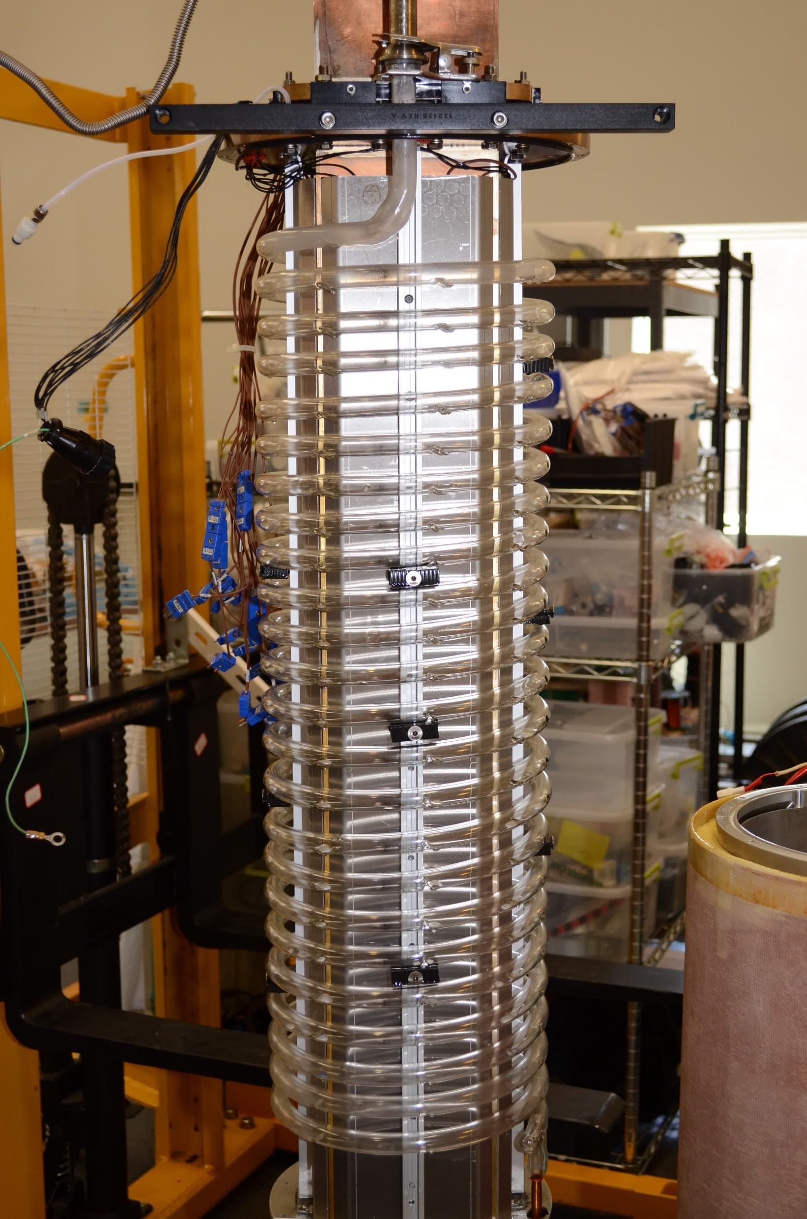
The first prototype was assembled at the University of New Hampshire in the late 1990s and early 2000s. We founded Xemed in 2004 to develop it into an instrument that a hospital can operate.
Reference: Ruset, Ketel and Hersman, Physical Review Letters 96, 053002 (2006), listed under Publications.
Rubidium density and the cooled extension
Higher rubidium density gives higher polarization rates. We raise the temperature of the liquid rubidium reservoir. This puts more rubidium vapor into the flowing gas. The spin-exchange rate between polarized rubidium and xenon nuclei rises with the rubidium density. Faster spin exchange allows more laser power to be used to polarize the rubidium.
Spin exchange also works in reverse. When the gas leaves the laser light, the rubidium depolarizes within milliseconds. The depolarized rubidium then begins to draw down the polarization of the xenon nuclei. We therefore extended the polarizing chamber near the gas exit. The wall of this extension is held at a much lower temperature than the polarizing section. Most of the rubidium vapor condenses on that wall while it is still in the laser light and still polarized. The xenon then leaves the laser light with little rubidium left to depolarize it.
Reference: US patent 7,928,359, listed under Patents below.
Heat removal and wall area
More laser power deposits more heat in the gas. Heat removal from a gas increases with the surface area or with the temperature difference. Here the temperature difference is limited. The heat-exchange surface must stay above the condensation temperature of rubidium, or the rubidium vapor density would fall. The design therefore needs more surface area.
Earlier designs minimized surface area and used blown glass. Our patented insight is that surface area and material must be balanced. The balance is between the surface area exposed to the gas, the thermal conductivity to a thermal reservoir, and the spin relaxation at the surface. Our polarizing chamber is a metal heat exchanger with added internal surface. Its walls and heat-exchange surfaces run parallel to the laser beam. The beam is collimated and aligned with the magnetic field. This alignment maximizes the spin polarization. A fast-flowing heat-exchange fluid behind the metal carries the heat to the thermal reservoir. The gain in production from removing the heat outweighs the loss from the added surface.
Our toolkit includes further options for the surfaces that face the gas. A thin glass cladding is one example. We choose among these options for each design.
Reference: US patents 7,928,359 and 8,405,022, listed under Patents below.
The laser
Optical pumping at this scale requires high-power laser light at the rubidium line, 795 nm. Laser diodes supply this power at low cost. However, their natural spectrum is much wider than the atomic line. We narrow a whole stack of diode bars in a single external cavity.
A stepped mirror makes the optical path from every bar to the diffraction grating equal. One cavity can then lock hundreds of emitters to the same wavelength. Our production lasers are capable of up to a kilowatt with this method. That power provides headroom for optimizing the operating parameters.
Reference: Zhu, Ruset and Hersman, Optics Letters 30, 1342 (2005), listed under Publications.
What it delivers
- Since 2010
- fully automated
- 40 to 50%
- xenon-129 polarization, measured in the bag
- 4 to 6 liters
- of polarized xenon per hour
The polarizer mixes its gases on board, automatically. The operator can adjust the mixture to balance polarization against production rate. Each run delivers up to three liters of polarized xenon, in up to four dose bags. The machine runs the production cycle automatically. It has on-board diagnostics and keeps a quality log for every batch.
The best day on record is March 22, 2021. The polarizer completed nine production runs in eight hours. It delivered 19 liters of xenon-129 at 50% polarization for funded research studies.
The instruments, the gas, and the support we offer are described under Products.
Patents
U.S. patents in force on the polarizer and its laser. They are assigned to the University of New Hampshire, where the method was invented. Each number links to the full record on Google Patents.
| Number | Title | Inventors | Granted or published |
|---|---|---|---|
| US 8,405,022 | Thermal management technology for polarizing xenon | Hersman | March 26, 2013Granted |
| US 7,928,359 | Thermal management technology for polarizing xenon | Hersman | April 19, 2011Granted |
| US 7,769,068 | Spectral-narrowing diode laser array system | Hersman, Distelbrink, Zhu | August 3, 2010Granted |
- US 8,405,022
Thermal management technology for polarizing xenon
Hersman
March 26, 2013. Granted.
- US 7,928,359
Thermal management technology for polarizing xenon
Hersman
April 19, 2011. Granted.
- US 7,769,068
Spectral-narrowing diode laser array system
Hersman, Distelbrink, Zhu
August 3, 2010. Granted.